VariCAD 2021 2.05 Win x64
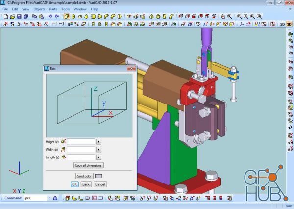
VariCAD is 3D / 2D CAD software primarily intended for mechanical engineering design. The comprehensive CAD software enables designers to quickly create, evaluate, and modify their models. The software is sold as one "fully loaded" package, with all features and functions, for one very affordable price. VariCAD delivers an excellent performance-to-price ratio, making it one of the smartest choices on the market today.
User Interface and System Environment
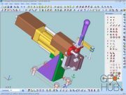
VariCAD's Graphical User Interface (GUI) has been designed to allow quick and intuitive 3D/2D orientation. It has been carefully tailored and tuned to reflect the thought process of a designer, so that ideas can be captured and communicated with a minimal number of steps. All commands were created with a focus on ease of use.
You can start by creating a 3D model and then use it to automatically create drawings files, or you can draw only in 2D. Designing in 3D is generally more "natural," in that it closely represents actual parts and assemblies. The 3D approach is usually more intuitive than 2D drafting. Models created in 3D are easily converted into conventional 2D documentation. VariCAD provides tools for 2D updates after changes of 3D models.
3D Modeling
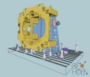
VariCAD provides a library of basic 3D shapes (like a box, cylinder, cone, etc.), which are easily modified by editing their dimensions. Solids can be created also by profile rotation, extrusion, or lofting. More complex tools include rotation blending between two profiles, lofting between a circle and rectangle or between different profiles, and creation of helical surfaces.
Solids can be added or subtracted, thus forming Boolean trees representing real mechanical parts. Boolean operations have options of automatic trimming (so called selective Boolean operations). Predefined operations like drilling of holes, face milling or groove milling are also available. Edges can be rounded or chamfered. VariCAD provides a lot of possibilities of solid transformations or their editing. Also, you can easily edit Boolean trees - either selecting solid parts from 3D, or selecting them from a list displaying structure.
Parameters and Geometrical Constraints
Although you can comfortably transform solids or their parts, you can optionally define geometrical constraints. Once defined, constraints allow you “to stick” object at defined location. More exactly, you can remove degrees of freedom of constrained objects. If other objects are changed or transformed, constrained object changes its position automatically. For instance, if you constrain a groove to the end of a shaft and the shaft length is changed, the groove remains in constant distance from the end edge. Constraints can be defined among elements of a solid, among entire solids or within a 2D profile creating a solid (for instance, by extrusion).
Download links:
Comments
Add comment
Tags
Archive
| « February 2026 » | ||||||
|---|---|---|---|---|---|---|
| Mon | Tue | Wed | Thu | Fri | Sat | Sun |
| 1 | ||||||
| 2 | 3 | 4 | 5 | 6 | 7 | 8 |
| 9 | 10 | 11 | 12 | 13 | 14 | 15 |
| 16 | 17 | 18 | 19 | 20 | 21 | 22 |
| 23 | 24 | 25 | 26 | 27 | 28 | |
Vote
New Daz3D, Poser stuff
New Books, Magazines
 2021-06-29

 1 044
1 044
 0
0

